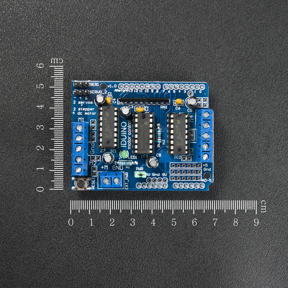

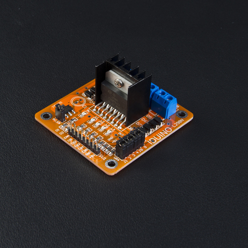
L293D Servo and Motor Controller Module
Description:
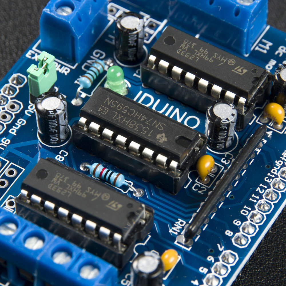
L293D is a monolithic integrated, high voltage, high current, 4-channel driver. Basically this means using this chip you can use DC motors and power supplies of up to 25 Volts, that"s some pretty big motors and the chip can supply a maximum current of 600mA per channel, the L293D chip is also what"s known as a type of H-Bridge. The H-Bridge is typically an electrical circuit that enables a voltage to be applied across a load in either direction to an output, e.g. motor. Features : 2 interface for 5V Servo connected to the Arduino"s high-resolution dedicated timer - no jitter. Can drive 4 DC motors or 2 stepper motors or 2 Servo. Up to 4 bi-directional DC motors with individual 8-bit speed selection. Up to 2 stepper motors (unipolar or bipolar) with single coil, double coil or interleaved stepping. 4 H-Bridges: per bridge provides 0.6A (1.2A peak current) with thermal protection, can run motors on 4.5V to 25V DC. Pull down resistors keep motors disabled during power-up. 2 external terminal power interface, for separate logic/motor supplies. Tested compatible for Arduino Mega, Diecimila and Duemilanove.
Specifications:
- Power Supply: 5VDC~36VDC
- 4H-Bridges: Provides 0.6A(1.2A peak current )with thermal protection, per bridge
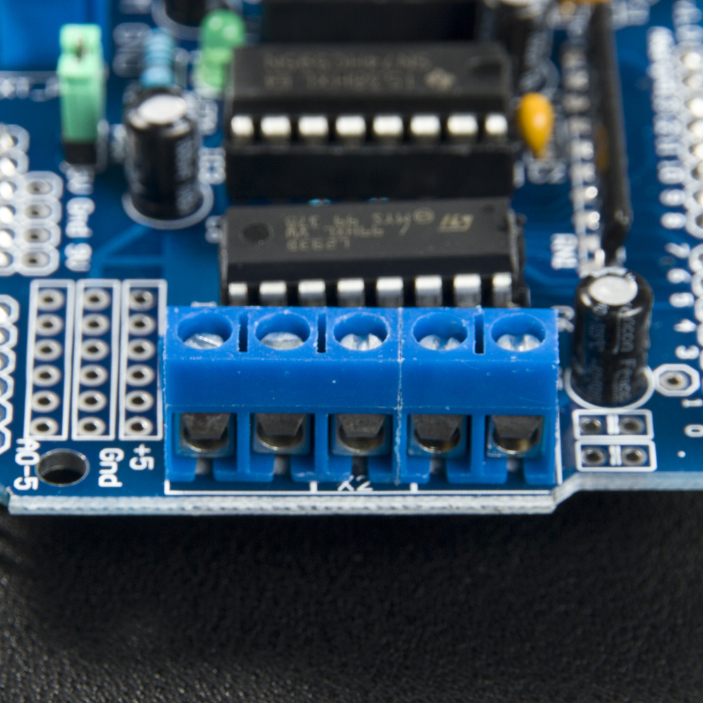
- External Terminal power Interface: 2
-
Dimensions:70*53*20mm
2. What pins are used on the motor shield?
All 6 analog input pins are available. They can also be used as digital pins (pins #14 thru 19)
Digital pin 2, and 13 are not used.
The following pins are in use only if the DC/Stepper noted is in use:
Digital pin 11: DC Motor #1 / Stepper #1 (activation/speed control)
Digital pin 3: DC Motor #2 / Stepper #1 (activation/speed control)
Digital pin 5: DC Motor #3 / Stepper #2 (activation/speed control)
Digital pin 6: DC Motor #4 / Stepper #2 (activation/speed control)
The following pins are in use if any DC/steppers are used
Digital pin 4, 7, 8 and 12 are used to drive the DC/Stepper motors via the 74HC595 serial-to-parallel latch
The following pins are used only if that particular servo is in use:
Digitals pin 9: Servo #1 control
Digital pin 10: Servo #2 control
3. Example
Here is a example to control a DC Motor through port M3.
// Adafruit Motor shield library // this code is public domain, enjoy! #includeAF_DCMotor motor(3); void setup() { Serial.begin(9600); // set up Serial library at 9600 bps Serial.println("Motor test!"); // turn on motor motor.setSpeed(200); motor.run(RELEASE); } void loop() { uint8_t i; Serial.print("tick"); motor.run(FORWARD); for (i=0; i<255; i++) { motor.setSpeed(i); delay(10); } for (i=255; i!=0; i--) { motor.setSpeed(i); delay(10); } Serial.print("tock"); motor.run(BACKWARD); for (i=0; i<255; i++) { motor.setSpeed(i); delay(10); } for (i=255; i!=0; i--) { motor.setSpeed(i); delay(10); } Serial.print("tech"); motor.run(RELEASE); delay(1000); }
Raspberry Pi 2017-11-01 00:08:32
Can this item (ST1138) be used with the Raspberry Pi? If yes, what would the connection look like?
Comment
Recommended Products
-
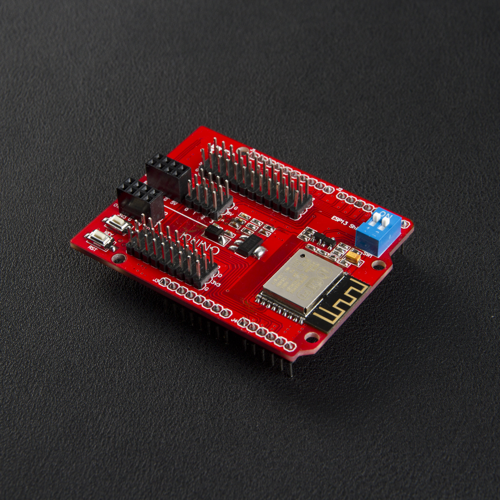 ESP8266 Wifi Shield For ArduinoItem No.: AD010
 -
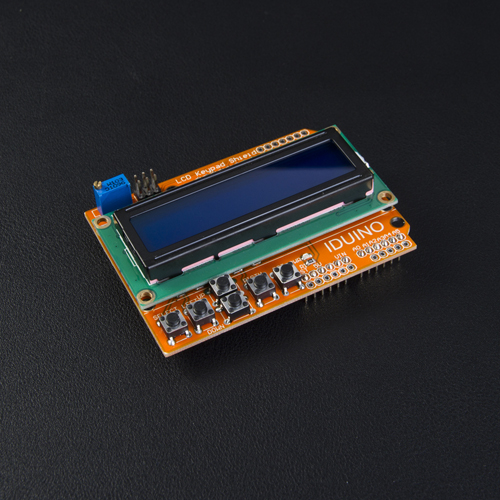 2×16 LCD ControllerItem No.: ST1113
 -
 Stepper Motor Controller ModuleItem No.: ST1112
 -
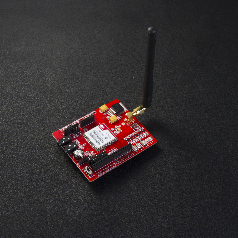 SIM900A GPRS/GSM ShieldItem No.: AD046
 -
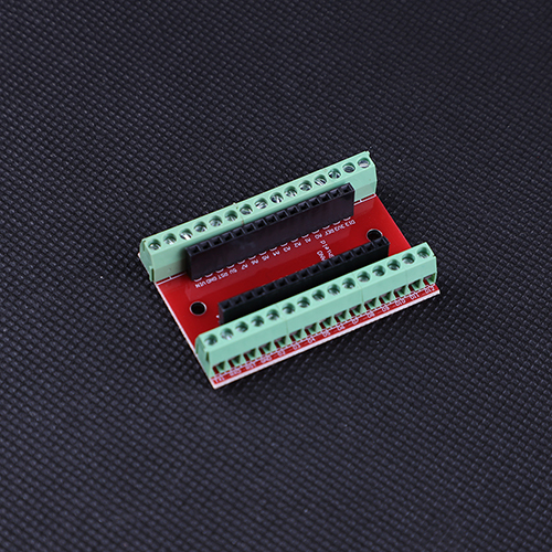 NANO 3.0 Controller TerminalItem No.: EX015
 -
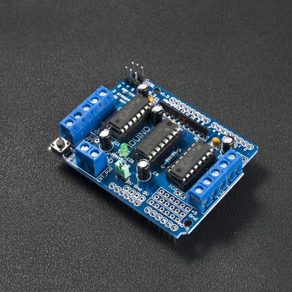 L293D Servo and Motor Controller ModuleItem No.: ST1138
 -
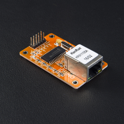 Ethernet Interface ModuleItem No.: ST1160
 -
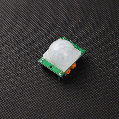 PIR Motion Detector ModuleItem No.: SE062
 -
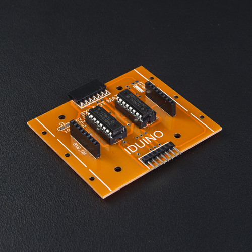 8×8 Dot matrix drive ModuleItem No.: ST1156
 -
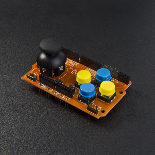 Joystick Controller ModuleItem No.: ST1124
 -
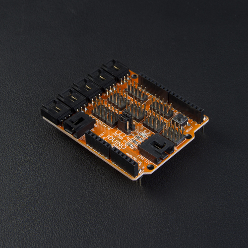 Sensor Expansion shield V4.0Item No.: ST1035
 -
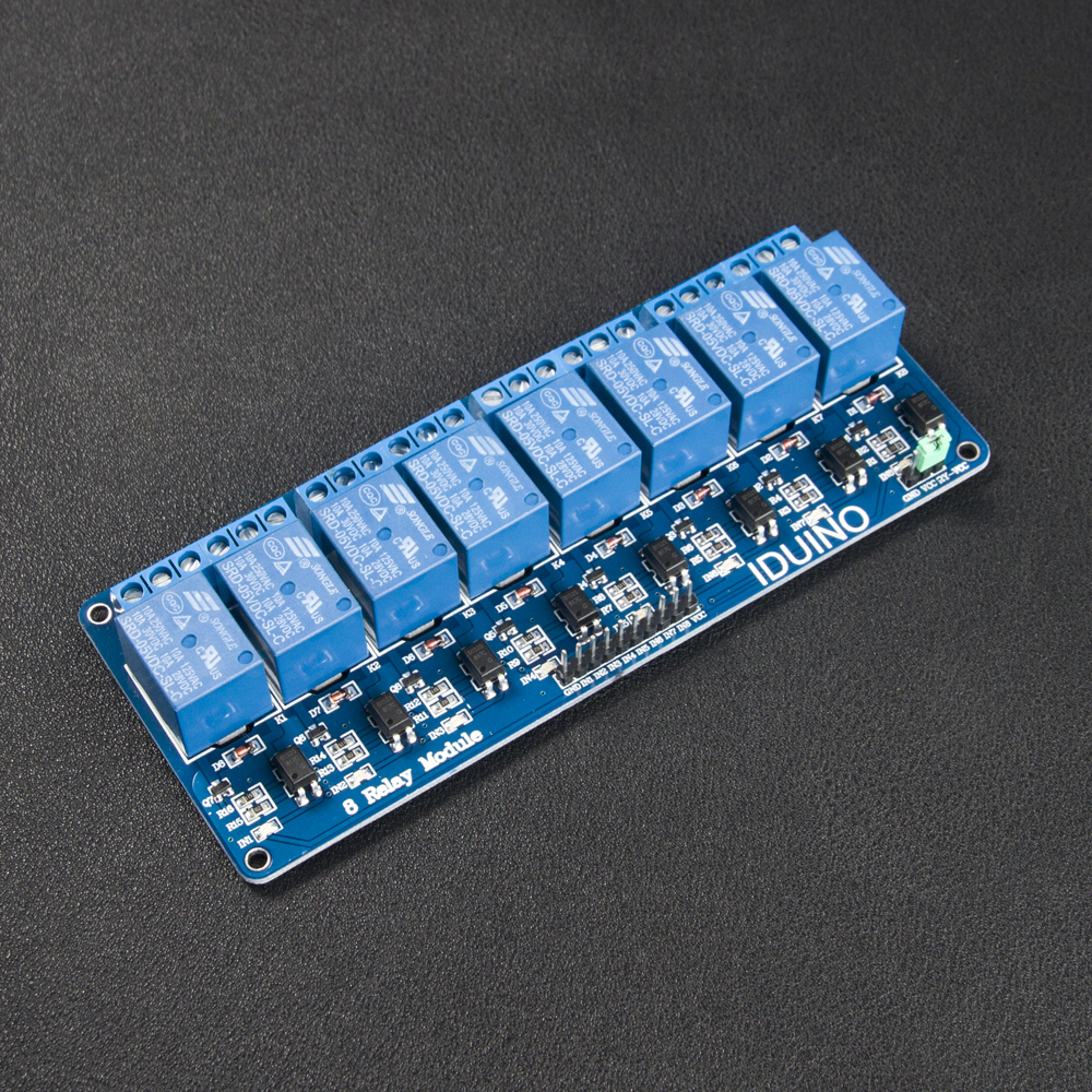 5V 8 Channel Relay Module Board for ArduinoItem No.: ME115
 -
 Data Log ModuleItem No.: ST1046
 -
 4× 5050 RGB LED ModuleItem No.: ME141
 -
 Ethernet W5100 R3 Shield Network BoardItem No.: ST1044
 -
 8×8 Full-color RGB LED Matrix Driver ModuleItem No.: ST1149